BlueSaab Amp pcb!

Previous Topic Next Topic
 
classic Classic list List threaded Threaded
25 messages Options
12
Reply | Threaded
Open this post in threaded view
|

BlueSaab Amp pcb!

Seth
Administrator


Here's what the "secret" 10 pin connector is for; it's a separate audio amplifier! If you follow the silkscreen values, it's setup to be a 2x gain. The volume level is loud. If you change the 2k resistors to 3.3k, it's now a 3.3x gain, and it's even louder (obviously).

Remove the 4 jumpers on the connector, and simply insert this module, lining up the pins. That's it! This module is pretty cheap to make, and easy to assemble (v1.0 was smaller parts and smaller area; v1.1 has spaced things out for less of a chance to bridge things).

PCB: https://oshpark.com/shared_projects/AXnbvpZZ
BOM: http://www.mouser.com/ProjectManager/ProjectDetail.aspx?AccessID=7386d4e698

Enjoy the tunes!

NC, USA
Reply | Threaded
Open this post in threaded view
|

Re: BlueSaab Amp pcb!

saab95
Excellent :-)

Is a double gain the recommended "setting" to make the volume comparable to the radio?

Will it be any problems with retrofitting this onto older boards, other than the soldering part?
Reply | Threaded
Open this post in threaded view
|

Re: BlueSaab Amp pcb!

Karlis
Administrator
Our tests have shown that with the AMP present in current configuration, the volume of BlueSaab is ~5dB louder than that of an IHU being in Radio mode. So, yes, I'd call the current configuration "recommended".

I'd let Seth chime in on the hardware part of the question.
2001 9-5 SE V6; 2006 9-5 Wagon; iOS; BlueSaab version = "latest and greatest" :)
Reply | Threaded
Open this post in threaded view
|

Re: BlueSaab Amp pcb!

Seth
Administrator
In reply to this post by saab95
saab95 wrote
Will it be any problems with retrofitting this onto older boards, other than the soldering part?
So this amp will only work with v5.x pcbs. The effort to retrofit it to older pcbs wouldn't be worth it, IMO. I mean, I'm not saying it's impossible, but let's just say that I wouldn't try to do it myself :)
NC, USA
Reply | Threaded
Open this post in threaded view
|

Re: BlueSaab Amp pcb!

saab95
I guess I'd have to cut the trace from the bt chip and solder on the wires from the amp... or just buy the parts for a ver5...
It's all that smd soldering that's holding me back ;-)
Reply | Threaded
Open this post in threaded view
|

Re: BlueSaab Amp pcb!

Seth
Administrator
Building a v5.x pcb isn't that hard. Don't let SMD scare you. The amp pcb is all SMD too!

I'll look into making an adapter board for the amp pcb so it's easier for v4.x and older to use it; but it would involve cutting the wires going to the CDC connector and soldering them to this adapter. Not pretty, and prob not necessary IMO, but it's certainly possible.
NC, USA
sbt
Reply | Threaded
Open this post in threaded view
|

Re: BlueSaab Amp pcb!

sbt
In reply to this post by Seth
I note this BoM is currently missing a 2.2kΩ resistor for R14. For example, could use Vishay P/N CRCW08052K20FKEA or KOA Speer P/N RK73H2ATTD2201F.

If you built a v5.0 BlueSaab PCB, you might have some Vishay 2.2kΩ resistors left over, especially if you switched any LED resistors to 10kΩ.

Same applies to the legacy amp PCB.

Cheers,
Sam.
9³ 5D MY02 - Stålgrå, AS3; iOS 16.1; BlueSaab v5.0-p1+Amp v1.1, SAAB-CDC v4.1 with mods
Reply | Threaded
Open this post in threaded view
|

Re: BlueSaab Amp pcb!

Seth
Administrator
sbt wrote
I note this BoM is currently missing a 2.2kΩ resistor for R14. For example, could use Vishay P/N CRCW08052K20FKEA or KOA Speer P/N RK73H2ATTD2201F.

If you built a v5.0 BlueSaab PCB, you might have some Vishay 2.2kΩ resistors left over, especially if you switched any LED resistors to 10kΩ.

Same applies to the legacy amp PCB.

Cheers,
Sam.
Just FYI, it hasn't been determined if R13/R14 are even necessary. I put a spot on the board for them just in case. (its easier to not populate shit vs add shit later)
NC, USA
sbt
Reply | Threaded
Open this post in threaded view
|

Re: BlueSaab Amp pcb!

sbt
Seth wrote
Just FYI, it hasn't been determined if R13/R14 are even necessary. I put a spot on the board for them just in case.
Thanks for clarifying that; I assumed they were given shown soldered in your photo in the first post. Haven't seen a schematic, but also assumed the set OCM voltage of 1V was more standard for audio applications than the default 1.65V in the THS4522 if neither R13 or R14 are fitted. If only R13 is fitted, doesn't that make the OCM voltage even higher than 1.65V?

Are you going to share the SCH/PCB files for the amp?
9³ 5D MY02 - Stålgrå, AS3; iOS 16.1; BlueSaab v5.0-p1+Amp v1.1, SAAB-CDC v4.1 with mods
Reply | Threaded
Open this post in threaded view
|

Re: BlueSaab Amp pcb!

Seth
Administrator
so if my math is right, and you use R13 & R14, with the 3.3v input, the voltage divider network should make the OCM voltage 1.01v, and will override the 1.65v default that the THS4522 has.

Like I said, I don't know if this difference is even necessary, I just put them there for the option to try.

Here's the link to v1.2 of the Amp pcb
https://www.dropbox.com/sh/iu1hkt37vpauakx/AABsG_yO2ar7IrMAawlP_C9na?dl=0
NC, USA
sbt
Reply | Threaded
Open this post in threaded view
|

Re: BlueSaab Amp pcb!

sbt
Seth wrote
Here's the link to v1.2 of the Amp pcb
Thanks for the upload. Have now built v1.1 as boards just arrived from OSH Park. I used the recommended 2kΩ resistors to set the gain, which seems to work OK; I still need phone volume set to the maximum, but at least radio volume is close and telephone call volume also tolerable.

I do have an issue where the BT module isn't started properly on power-up with the amp fitted (symptoms are that neither BT led flashes or lights, and the module is not discoverable/connectable). I've built two amp shields and they both exhibit this behaviour, so I'm not sure it's the (new) hardware. It's pretty consistently a problem with the amp fitted, and never a problem without. I've tried loading the BT configure software to the module, but this works fine everytime the module is powered up; the issue only affects the SAAB-CDC software.

Fortunately I can reproduce it on the bench with USB connection to UPLOAD, so I'm working on adding some more logging around the initialisation of the BT module. Hardware version detection is working correctly and v5.0 is reported from RN52impl::initialize(), so my suspicion that the additional drain of the amp at power up was taking the analogue sense voltage out of range and skipping the correct RN52 power up sequence was incorrect.

Suggestions for further debugging welcome.


9³ 5D MY02 - Stålgrå, AS3; iOS 16.1; BlueSaab v5.0-p1+Amp v1.1, SAAB-CDC v4.1 with mods
Reply | Threaded
Open this post in threaded view
|

Re: BlueSaab Amp pcb!

Seth
Administrator
Sam,

If you haven't, clean any residual flux off the pcbs using lots of alcohol and a toothbrush or similar. Flux can conduct if not removed.

The amp pcb only draws like 5mA so I seriously doubt it's causing the analog read to mess up.

The weird thing is, the BT lights should always be flashing; the rn52 never goes to sleep (not yet; we'll work on putting it to sleep in the future for better power savings). Since the rn52 is not supposed to be asleep, it sounds like something else is going on.

Does the module work fine after the first initial successful connection? If it's only an issue at initial power on, then yes, maybe there's an issue with the analog read not reading properly...so that leads me back again to 3.3 rail being off due to excess flux or something.

you can post more (clear) pics if you want of the module and amp pcb.
Seth
NC, USA
sbt
Reply | Threaded
Open this post in threaded view
|

Re: BlueSaab Amp pcb!

sbt
Seth wrote
The weird thing is, the BT lights should always be flashing; the rn52 never goes to sleep (not yet; we'll work on putting it to sleep in the future for better power savings). Since the rn52 is not supposed to be asleep, it sounds like something else is going on.

Does the module work fine after the first initial successful connection? If it's only an issue at initial power on, then yes, maybe there's an issue with the analog read not reading properly...so that leads me back again to 3.3 rail being off due to excess flux or something.
Thanks; I'll have another go with flux cleaning (although already did this). Also, both shields show the issue, and checking the 3.3V supply at the shield jumper, there's no drop in voltage with the shield fitted. Also, according to the startup log, the hardware is always being correctly detected as v5.0, even when the BT module doesn't power up. Given it's only happening with the SAAB-CDC software and not the BT configuration tool, I'm leaning towards a marginal timing issue or something.

The issue only happens from power on. If the BT module starts, it keeps working. I can cheat by waiting for the module to start before plugging in the amp.

More investigation needed. I did paste shield pics in the "Show your module" thread, but if they're not detailed enough can post close ups. Since both shields I made behave in exactly the same way, I'd be surprised if it's them. I guess it could be an undiagnosed issue with the main module.

Thanks,
Sam.
9³ 5D MY02 - Stålgrå, AS3; iOS 16.1; BlueSaab v5.0-p1+Amp v1.1, SAAB-CDC v4.1 with mods
Reply | Threaded
Open this post in threaded view
|

Re: BlueSaab Amp pcb!

Seth
Administrator
I did see those pics, but if you wanna take closer, clear pics of both sides of the boards, I'll look at them.

I'm wondering if it's something to do with the amp pcbs you built; not trying to say you screwed anything up, but I wouldn't mind taking another look :) Maybe v1.1 has a problem I don't know about...but you're right, it does sound like the issue is related to the amp pcb being plugged in and nothing else. Very weird.

Thanks for hanging in there with these bumps in the road!
Seth
NC, USA
sbt
Reply | Threaded
Open this post in threaded view
|

Re: BlueSaab Amp pcb!

sbt
Seth wrote
... it does sound like the issue is related to the amp pcb being plugged in and nothing else. Very weird.
I now have a software fix for this that works consistently, which gives me confidence that the hardware is OK, but is now consistently exposing a timing problem in the software around the BT initialisation with the PWREN pin.

The issue also explains why the RN52 configuration doesn't work in the SAAB-CDC software. I believe I have a fix for this too, which will avoid the need for the separate RN52 code upload and configuration steps (at least for boards with the 9600 baud hardware force). I need to do more testing, but I'll add a pull request to Karlis's repo when it looks good.

Thanks for all the support here; it's even better than you usually get for a paid product.

Cheers,
Sam.
9³ 5D MY02 - Stålgrå, AS3; iOS 16.1; BlueSaab v5.0-p1+Amp v1.1, SAAB-CDC v4.1 with mods
Reply | Threaded
Open this post in threaded view
|

Re: BlueSaab Amp pcb!

Karlis
Administrator
Hmm, ok. I have never seen this issue happening before. Here are a couple of things I would be interested to see:

*) What's the "%" setting on RN52? This can be accessed via uploading RN52 programming code and issuing "G%" command.

*) On certain hardware revisions, RN52 PWREN pin needs to be pulled high in order to power it on. RN52 programming code keeps this pin high at all times, that's why this particular issue doesn't manifest itself with programming code.

*) Hardware revision is being calculated as an average of ten analogReads from HW check pin. This is done in RN52impl.cpp.

*) A test would be to see what the 'hwRevisionCheckValue' value is after the calculations are made. This can be done by simply adding "Serial.println(hwRevisionCheckValue);" right above line #117.
2001 9-5 SE V6; 2006 9-5 Wagon; iOS; BlueSaab version = "latest and greatest" :)
sbt
Reply | Threaded
Open this post in threaded view
|

Re: BlueSaab Amp pcb!

sbt
Thanks for the follow-up on this.

Karlis wrote
Hmm, ok. I have never seen this issue happening before. Here are a couple of things I would be interested to see:

*) What's the "%" setting on RN52? This can be accessed via uploading RN52 programming code and issuing "G%" command.
RN52 programming mode
CMD
0084

Karlis wrote
*) On certain hardware revisions, RN52 PWREN pin needs to be pulled high in order to power it on. RN52 programming code keeps this pin high at all times, that's why this particular issue doesn't manifest itself with programming code.
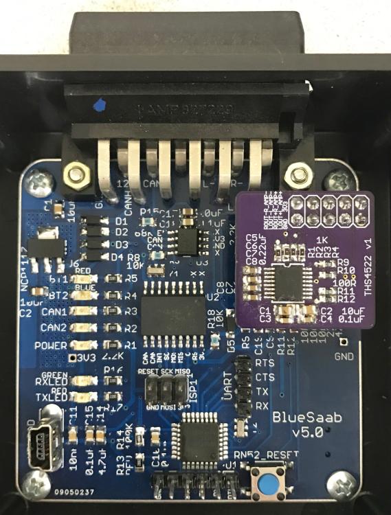
I have version 5.0, which is always detected correctly. It would explain why the issue only happens with SAAB-CDC.

Karlis wrote
*) Hardware revision is being calculated as an average of ten analogReads from HW check pin. This is done in RN52impl.cpp.

*) A test would be to see what the 'hwRevisionCheckValue' value is after the calculations are made. This can be done by simply adding "Serial.println(hwRevisionCheckValue);" right above line #117.
As above, the version is always correctly detected. I believe the issue relates to the timing for the enable, since time.pulse() holds the pin low for 3000ms before pulling it high for 3000ms. By replacing
time.pulse(BT_PWREN_PIN,3000,0);
 with
time.pulseImmediate(BT_PWREN_PIN,3000,1);,
 I can always get the module up, as this pulls the pin high straight away. However, for completeness, the number returned is 168, right inside the range for version 5.0.

Using time.pulse() or pulseImmediate() also explains why the config commented out later couldn't work; the module isn't awake when that code section is reached (it's not enabled until the time.update() calls are reached in loop()). I've a working mod that uses synchronous calls to digitalWrite to fix this.

There are some robustness issues with Tim Otto's code in the RN52driver parseCmdResponse code that manifest themselves with truncated or otherwise invalid responses from the RN52, such as when changing baud or rebooting. If the RN52 stops sending new characters when the parser is waiting for more to complete an expected response, the system effectively ends up in an infinite loop (but it won't trigger the watchdog, since the loop() still executes).

I suspect it's the delay of module power enable and starting the update() loop that reads the serial port overlapping that are causing the problem with startup I reported. I think they are also the cause of issue #15.

Still more to do.

Cheers,
Sam.
9³ 5D MY02 - Stålgrå, AS3; iOS 16.1; BlueSaab v5.0-p1+Amp v1.1, SAAB-CDC v4.1 with mods
sbt
Reply | Threaded
Open this post in threaded view
|

Re: BlueSaab Amp pcb!

sbt
sbt wrote
There are some robustness issues with Tim Otto's code in the RN52driver parseCmdResponse code that manifest themselves with truncated or otherwise invalid responses from the RN52, such as when changing baud or rebooting. If the RN52 stops sending new characters when the parser is waiting for more to complete an expected response, the system effectively ends up in an infinite loop (but it won't trigger the watchdog, since the loop() still executes).
Clarification: further work shows that while issues listed above are real, the root cause is sending the R,1 reboot command while PWREN pin is low. This prevents the reboot and the module becomes unresponsive after that. Having fixed that, I can now fully programme the RN52 on startup without relying on the separate RN52-BT-PRG sketch.

Now looking at some data mode concerns.
9³ 5D MY02 - Stålgrå, AS3; iOS 16.1; BlueSaab v5.0-p1+Amp v1.1, SAAB-CDC v4.1 with mods
Reply | Threaded
Open this post in threaded view
|

Re: BlueSaab Amp pcb!

Seth
Administrator
Don't beat yourself up too bad over the bad rn52 code; it's nobody's fault but Microchip because their documentation, while quite complete vs anything else, STILL SUCKS. It lacks many things, such as all LED flashing mode codes, and problems like you just mentioned (reboot while pwren pin low), as well as another problem we found; if the A0 pin on rn52 is held high, the module can't be powered on.

Eventually we'll figure out all the quirks, and then the EOL the module :-P

On Thu, Dec 15, 2016 at 7:28 AM, sbt [via BlueSaab Forum] <[hidden email]> wrote:
sbt wrote
There are some robustness issues with Tim Otto's code in the RN52driver parseCmdResponse code that manifest themselves with truncated or otherwise invalid responses from the RN52, such as when changing baud or rebooting. If the RN52 stops sending new characters when the parser is waiting for more to complete an expected response, the system effectively ends up in an infinite loop (but it won't trigger the watchdog, since the loop() still executes).
Clarification: further work shows that while issues listed above are real, the root cause is sending the R,1 reboot command while PWREN pin is low. This prevents the reboot and the module becomes unresponsive after that. Having fixed that, I can now fully programme the RN52 on startup without relying on the separate RN52-BT-PRG sketch.

Now looking at some data mode concerns.
2001 9-3 Aero, AS3+tape; SGS 5, Android M 6.0.1; BlueSaab v5.0-p1+Amp v1.1, SAAB-CDC 4.0-p1


If you reply to this email, your message will be added to the discussion below:
http://bluesaab-forum.2349123.n4.nabble.com/BlueSaab-Amp-pcb-tp737p871.html
To start a new topic under Hardware, email [hidden email]
To unsubscribe from Hardware, click here.
NAML

NC, USA
sbt
Reply | Threaded
Open this post in threaded view
|

Re: BlueSaab Amp pcb!

sbt
Seth wrote
Don't beat yourself up too bad over the bad rn52 code;
Not beating anyone; while the doco's not 100% (e.g. I'd like more detail on extended feature functions such as bit 10), it's the RN52 library code from Tim Otto I'm wrestling with. There are still too many "TODOs" and other missing features/poor interface design problems in this third party library (note I'm not referring to Karlis's code here).

Anyway, pressing on.
9³ 5D MY02 - Stålgrå, AS3; iOS 16.1; BlueSaab v5.0-p1+Amp v1.1, SAAB-CDC v4.1 with mods
12