BlueSaab v5.0 released!

Previous Topic Next Topic
 
classic Classic list List threaded Threaded
15 messages Options
Reply | Threaded
Open this post in threaded view
|

BlueSaab v5.0 released!

Seth
Administrator
This post was updated on .
Here's version 5.0 of the hardware!

BlueSaab v5.0 OSHPark link

BlueSaab v5.0 Mouser BOM

This version uses 0805 resistors and caps to save space, and make room for more things.
Removed the DFU switch; no longer needed since using signal diodes now.
Added some more bypass caps for power filtering.
Switched to SN65HVD234 for higher temp rating and future sleep mode.
Added 10pin connector...for future use ;)

*IN ORDER FOR YOU TO GET SOUND, THE 4 COLUMNS ON THE 10PIN HEADER NEED JUMPERS FROM TOP TO BOTTOM AS SHOWN IN THE PICTURE*
BUT  DON'T SHORT THE LAST COLUMN ON THE RIGHT!!
THOSE ARE 3.3V AND GND. YOUR MODULE WILL NOT WORK!!

NC, USA
Reply | Threaded
Open this post in threaded view
|

Re: BlueSaab v5.0 released!

Karlis
Administrator
Someone give that man a beer! No - make it ten!

Great job Seth! :)
2001 9-5 SE V6; 2006 9-5 Wagon; iOS; BlueSaab version = "latest and greatest" :)
Reply | Threaded
Open this post in threaded view
|

Re: BlueSaab v5.0 released!

Da Bear
In reply to this post by Seth
Ordering this board right now.
Great work!

Sorry I haven't been contributing the last months, real life came in the way :/

/Björn
Saab 9-5 Aero MY01 AS3 - 270hp/240hp Biopower
Saab 9-5 SE    MY00 AS1 - 210hp+
Reply | Threaded
Open this post in threaded view
|

Re: BlueSaab v5.0 released!

Da Bear
Just noticed this.
Why all the holes? It's not necessary, imho.

Saab 9-5 Aero MY01 AS3 - 270hp/240hp Biopower
Saab 9-5 SE    MY00 AS1 - 210hp+
Reply | Threaded
Open this post in threaded view
|

Re: BlueSaab v5.0 released!

Seth
Administrator
maybe not 100% necessary; they tie the top & bottom 3.3v nets together and near the vreg, that's good for heat dissipation.
NC, USA
Reply | Threaded
Open this post in threaded view
|

Re: BlueSaab v5.0 released!

Seth
Administrator
Also, just FYI, I literally this minute just updated the BOM for 5.0+ to use 10k resistors for all LEDs (and changed the green led to a different green one that's brighter). So use 10k for the leds, not 2.2k as the pcb says. It won't hurt to use 2.2k but the LEDs are bright as shit; 10k brings them down to less-than-the-sun brightness.
NC, USA
sbt
Reply | Threaded
Open this post in threaded view
|

Re: BlueSaab v5.0 released!

sbt
This post was updated on .
Seth,

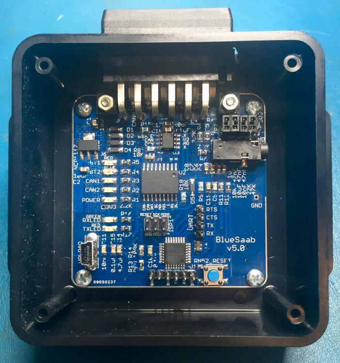
Great job on this. Just built v5.0 and it works! I will go the amp module since the volume's a bit low, but otherwise good.

I ordered the BoM before you revised the LED resistors, but there were enough spare 10ks to replace all except R16, which is fine with 2.2k and the originally spec'd green LED.

Couple of errata for the current BoM:

* The "Customer Part No" for the first item, "Thick Film Resistors - SMD 1/8watts 10Kohms 1%" includes R13, but this is a 20k resistor on schematics, and is included as item 6 on the BoM. Gave me an extra spare 10k for R17 though, so.

* The CPN for the third item "Multilayer Ceramic Capacitors MLCC - SMD/SMT 50volts 0.1uF X7R 10%" has "C5" instead of "C3".

* The CPN for the 19th item "Multilayer Ceramic Capacitors MLCC - SMD/SMT 50volts 10000pF X7R 10%" now includes C23, but v5.0 doesn't have this component?

* It looks like the part number for the Mini USB socket "RN52_FIRMWARE" has changed.

Building:

* The specified ATMEGA328P doesn't ship with a boot loader. That's fine, but it's handy to know this as this is the first thing needed to upload before uploading the SAAB-CDC software and the UPLOAD USB socket can't be used for this part; another arduino (using the ISP1 header) or FTDI interface (using the six pin header below the ATMEGA328P) is needed. EDIT: Incorrect in terms of FTDI; according to Seth, only ISP1 can load the bootloader.

* The mic socket has location bumps on the base, but there are no holes in the PCB (as for the RN52_Firmware socket). I just cut them off the socket, but it would be nice to have them to locate the socket precisely on the board. I see that in the current layout, that's not possible due to the location of the BT module.

* I used solder paste and "skillet reflow" to do the surface mount components on the top of the board. This was a time saver and the quality is better than hand soldering. This included the reset button and mic socket. I then hand soldered the bottom side surface mount components. It's important to precisely place the fine pitched BT module and FT interface chip before drag soldering (which I think is the best approach). I tacked the corners with small amounts of paste and checked precise alignment before applying paste to the rest of the pins.

* Lastly, I added all the through hole components (headers/sockets/connectors). I only populated the ISP1 header, as I wasn't using the FTDI (the six pin header below the ATMEGA328P) option. Either one of the other is needed depending on whether an FTDI programmer or ICSP (another arduino, e.g.) is used to load the bootloader.

* The RN52_FIRMWARE socket and UART header don't need to be populated, if everything works. Once the bootloader is installed, all the programming can be done via UPLOAD.

EDIT: For this version, follow the steps from 13 on the RN52 configuration tutorial, after connecting via the USB port BEFORE loading the SAAB-CDC software. This sets the RN52 correctly.

Testing:

* When the board is plugged in via ISP1 or UPLOAD, the Power LED should turn on.
* When uploading the code, the RXLED and TXLEDs should blink.
* When the software's been uploaded, the BT1 and BT2 LEDs should flash alternately, signalling the BT module is ready to pair.
* When connected to the car, one of the CAN LEDs should glow faintly (it's really blinking rapidly) as well, this signals there is traffic on the I-BUS.

* Once a phone is paired, switching on the radio the SID should chime. Once the CDC source is selected, the module will pair to the phone. Another softer beep should come through the speakers to signal pairing. EDIT: This pairing sound won't happen once the RN52 configuration is done; these sounds are disabled. I've noticed that playback starts and stops automatically with IHU on/off, which is nice.

* Without an amp module, the volume is low at default levels for IHU/phone. If things seem to be working, e.g. the phone's playing music, the SID indicates "CD PLAY 01", but no sound, try turning up the volume on the IHU and your phone. EDIT: Again, by default the RN52 module volume is low. The RN52 configuration process should ameliorate this a bit.

Cheers,
Sam.
9³ 5D MY02 - Stålgrå, AS3; iOS 16.1; BlueSaab v5.0-p1+Amp v1.1, SAAB-CDC v4.1 with mods
Reply | Threaded
Open this post in threaded view
|

Re: BlueSaab v5.0 released!

Seth
Administrator
Hi Sam,

So Mouser's project/bom tool SUCKS. If you use the exact same part in 2 different projects, BOTH projects update when you change the customer part number OR quantity; how shitty is that?!?! I've contacted them about this; they don't seem to care which is abysmal. So that's probably why you see a discrepancy with quantities or part numbers not matching...sorry about that. When in doubt, follow the silkscreen; it was right when I laid it out :)

I had to compromise cutting off the mic "nipples" on the bottom due to the layout change with the 10 pin header...just running out of room! I don't wanna make the pcb bigger; makes the cost go up. The mic doesn't work right now anyway (not sure if it ever will...), so you don't even need it at this point (or the caps/resistors relating to it).

The usb upload plug is only useful once you have a bootloader installed on the 328. you HAVE to use another arduino or AVR ISP tool to burn the bootloader. Then you can use either the FTDI header or the USB upload plug.

Thanks for the feedback, though :)
Seth
NC, USA
sbt
Reply | Threaded
Open this post in threaded view
|

Re: BlueSaab v5.0 released!

sbt
Seth,

No worries; sorry for the confusion on the FTDI; I thought that was for the bootloader.

I used the schematic as the source of truth when building, so I think everything turned out fine.

Notwithstanding the issues with Mouser, it's still easier than specing and selecting all those parts separately; it's a real time saver at the front end of a build and I'd expect less scope for error; after all, Mouser have heaps of 328s to choose from; no guarantee I'd choose the right one. I appreciate you providing this.

Would separate accounts at Mouser help?

Cheers,
Sam.
9³ 5D MY02 - Stålgrå, AS3; iOS 16.1; BlueSaab v5.0-p1+Amp v1.1, SAAB-CDC v4.1 with mods
Reply | Threaded
Open this post in threaded view
|

Re: BlueSaab v5.0 released!

Iprouteth0
In reply to this post by Seth
The link for the bluesaab v5.0 for OSHpark appears to be dead.  
Reply | Threaded
Open this post in threaded view
|

Re: BlueSaab v5.0 released!

Seth
Administrator
Reply | Threaded
Open this post in threaded view
|

Re: BlueSaab v5.0 released!

Nickhe
In reply to this post by Iprouteth0
Reply | Threaded
Open this post in threaded view
|

Re: BlueSaab v5.0 released!

Seth
Administrator
this is actually v5.1. Not officially released only because neither Karlis or I have actually made one yet to make sure they work :P I don't doubt it will, but just FYI.
NC, USA
Reply | Threaded
Open this post in threaded view
|

Re: BlueSaab v5.0 released!

danbr890
Hey,

I just ordered the v5.1 board from oshpark.

Is there an updated BOM for it as well? Wondering what the 555 timer is for...
2005 9-5 Aero Wagon,  past: '93 9000 aero, '89 SPG
Reply | Threaded
Open this post in threaded view
|

Re: BlueSaab v5.0 released!

Karlis
Administrator
555 timer is for "emergency use only". If stuff goes haywire, this chip will cut the power to the whole module thus reseting it.

Currently we rely on a watchdog timer in the code that asserts that one loop of the code has to complete within 30ms.

So 555 is just as yet another "security" layer.
2001 9-5 SE V6; 2006 9-5 Wagon; iOS; BlueSaab version = "latest and greatest" :)