BlueSaab Legacy Amp PCB?
12
12
|
Administrator
|
This post was updated on .
See this facebook post here
But the gist of it is, it's a pass-through power board with an amp chip to boost the volume from the BlueSaab to the car. What is the interest in it? Any? It turns out it's prob more expensive than most people wanna pay, but lemme know! I'll either finish the design, make changes, or scrap it :P Seth
NC, USA
|
|
This is really cool and I'm interested.
The car-side CDC conncetor, is it the same as i this picture and you will have to solder on your own wire from the amp board? https://www.autopartsapi.com/eEuroparts.com/images/parts/lg_a94507c1-3f6f-4d1f-972c-9f75fc38deb9.jpg The only downside I can spot is if you would have two large boxes in the trunk... A solution is to minimize the board and use a large heat shrink tubes.... The new car side CDC connector can be wired via ethernet cable if the wire gauge is large enough to handle the current load? |
|
This will be a nice add-on until I get my ver > 5 board :-D
|
|
Administrator
|
In reply to this post by saab95
Yes, so that cable you linked to has the car side connector. That would probably be the easiest way to make the connection, but also more expensive than option B: buying the connector and pins, and crimping the pins onto 8 wires, and inserting the pins into the connector. I've done route B and it's not bad, but also a little time consuming. But I have a cable I made like this and it works great.
So this "side project" isn't finalized; it's small enough that yeah, you could probably just put a sleeve of heatshrink over the whole thing and call it good. I wouldn't call it ideal, but it would work just as well. As far as using ethernet goes...those wires are pretty small, and since this device is a pass-thru for power, I wouldn't recommend it. I think the car uses 16ga wire for power and ground, and 18ga for all others. But a good idea, though :) This module itself will probably pull something like 25mA, but the module on the other side will pull more than that (if it's a BlueSaab module, less than 100mA).
NC, USA
|
|
As an interim solution until the main board supports amp, covering an external amp board with heat shrink tubing would work fine for me :-)
Regarding the cable I linked to: I was merely inquiring if this was the correct connector. Where can I buy one of these connectors? Ethernet cable, probably not a good idea in the long run to use such small cables... A thought: Is it possible to fit the amp board inside the existing box and desolder the conncetor. Solder wires from the main board to the amp, solder wires from the amp board to the connector. For this to work you'd to fit and fix the amp inside the box and bend som of the pins on the connector... |
I was thinking on similar lines; if you mount the amp board upside down at the top of the box with the CDC connector mounted as per the design, then you just need a few short leads to bridge the two boards together inside the box and the connector should still go through the same hole. This would save a lot on parts and connectors; further, it might be possible with a small variation to omit the power reg on the amp board and associated components and get 3.3v from one of the header pins (I think some of the earlier versions didn't have diode protection on all headers; 5.0 does).
9³ 5D MY02 - Stålgrå, AS3; iOS 16.1; BlueSaab v5.0-p1+Amp v1.1, SAAB-CDC v4.1 with mods
|
|
Administrator
|
Well the whole problem with <5.0 designs is that you have to break the signals from the rn52 to the cdc connector. That is not a easy thing to do. I supposed you could try to desolder the speaker pins on the CDC, bend them away, solder wires to an amp pcb v1.1, solder wires back to the bluesaab pcb, solder power and ground...but it's gonna be ugly. and a LOT of work.
I'm not saying it won't work. But I'm sure as hell not gonna make them like that for someone :)
NC, USA
|
|
Administrator
|
In reply to this post by saab95
connector housing pins you're *supposed* to use a crimp tool for these pins but I just used a pair of pliers and then soldered the wires for good measure. I wasn't able to get the pins back out, so be sure you put the wires where you want!!
NC, USA
|
|
In reply to this post by Seth
Seth, I was not suggesting using the amp pcb 1.1. I was suggesting a way to reduce the cost and messiness for retrofitting the legacy amp board inside the case, avoiding the need for any more connectors. You just need a pcb and components, so it shouldn't be much more than the amp v1.1, except due to square inches. But, you have to remove/desolder the CDC entirely from the old bluesaab module, and then re-solder it to the legacy amp. With the legacy amp board mounted upside down above the orginal PCB, the connector can still go through the hole in the plastic box. See extremely crummy diagram: 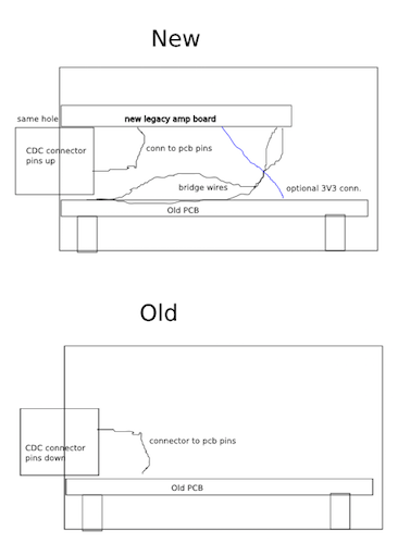 There should be enough wiring harness available in the car to twist through 180 degrees when mounting the box. The only additional wiring is 8 through hole connections with short lengths of hookup wire between the pcb holes on the edge of the legacy amp pcb and the pcb holes on the old module board where the CDC connector used to be. The only "messy" step is to desolder the connector; there's no cutting, bending or even trace cutting; all the bridge wiring is through-hole soldering (unless you delete the power supply and pickup 3.3V from the original board). Also, there's no more soldering than building the legacy amp outside the original BlueSaab with a flylead.
9³ 5D MY02 - Stålgrå, AS3; iOS 16.1; BlueSaab v5.0-p1+Amp v1.1, SAAB-CDC v4.1 with mods
|
|
Administrator
|
I see what you mean there, but then the issue becomes, how do you mount the new amp pcb? There aren't any mounting bosses on the lid and the cdc connector requires a helluva lot of force to connect/reconnect.
Sorry, not trying to shoot your (or anyone else's) ideas down, but it doesn't seem very feasible at this point. I totally understand that people (probably) won't wanna spend ~$40 for an external amp board, and I totally get that it would be ideal to cram it into the existing enclosure...but the fact remains that <5.0 pcbs just weren't designed with an amp in mind :)
NC, USA
|
|
Sure, the pcb mounting is a serious concern. There are two options I can see:
1) mod the legacy amp pcb so that it's wider and extends to the mounting bosses and mount the orginal board upside down at the top of the box. Then, the connect/disconnect strain goes directly to the bosses; or at least two of the them near the connector. 2) stick with the plan I suggested, but replace the internal mounting screws for the CDC connector with longer screws and bushes that clamp the two boards together with the connector as well.
9³ 5D MY02 - Stålgrå, AS3; iOS 16.1; BlueSaab v5.0-p1+Amp v1.1, SAAB-CDC v4.1 with mods
|
|
In reply to this post by Seth
The first favor I did myself was snipping off those little nubs on the connector. The fit is still plenty tight. |
|
Administrator
|
In reply to this post by sbt
It's also going to be necessary to run all 8 wires from the bluesaab pcb to the legacy adapter; the legacy adapter will "pass thru" the car power, gnd, and i-bus connections. I'm not convinced that using longer screws to mount things will be enough support for the connector. The bosses are only 1/4" high, and as it is now, the CDC is almost in line with them, which makes for great support. When you move the connector to go through a vertical screw mount and then push on the top, the boss's are not gonna hold that torque at all. Honestly, I would suggest the best way at the moment is to desolder the 4 speaker pins, bend them up and out, and then solder wires as necessary. Obviously you're still gonna need to solder 10 wires; 4 speaker in, 4 speaker out, and 3.3v and gnd to the amp pcb. it's a lot of work. If people want, I can post the pcb as-is, and they can go the heat shrink method...or we can brainstorm some more...or people can just make a v5.0+ module  
NC, USA
|
Well that's a similar effort if you build a whole new passthrough adapter and attach a fly lead You could extend the screws through to the lid, and add nuts once the lid's on. Not as pretty, but probably still neater than adding a second box. Or stick with option 1; it places the connector in the same relation to the bosses as the original. I assume the fully external module with connectors will appeal to people who got their modules from someone else and just want a plug in. Whereas if I had an earlier one, I'd be looking for a cheap in-box mod. In that case, I'd want the option 1 version that's wider, and the option to leave out the 3.3v components and bridge from the board. I wouldn't have an issue with soldering two ends of 9 wires. Well I've been throwing out ideas to help reduce the costs, but I guess it really depends on people who actually have a pre-5.0 module and their appetite for soldering vs cost so I'll leave the conversation to them.
9³ 5D MY02 - Stålgrå, AS3; iOS 16.1; BlueSaab v5.0-p1+Amp v1.1, SAAB-CDC v4.1 with mods
|
|
Administrator
|
So this is what I've come up with; it's just a tweak to the existing PCB amp v1.1, so I made it rev 1.2.
This just has some pads exposed on the bottom, which you will solder the pins on the CDC to, after some bending. (see pics below). Once you bend the 4 pins and the amp pcb is assembled, you solder 6 wires to the bluesaab pcb from the old cdc pin holes and 3.3v and gnd. then solder this amp pcb to the pins, upside down. then solder the 6 wires to the amp pcb. YOU WILL HAVE TO BEND THE PINS UP, OR BEND THE MCP2515 CRYSTAL OVER SO THE PCB CAN FIT. 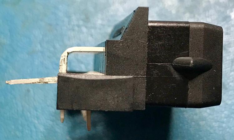 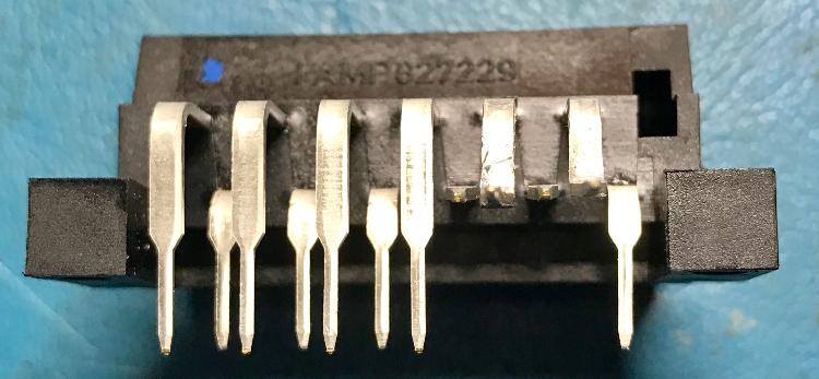 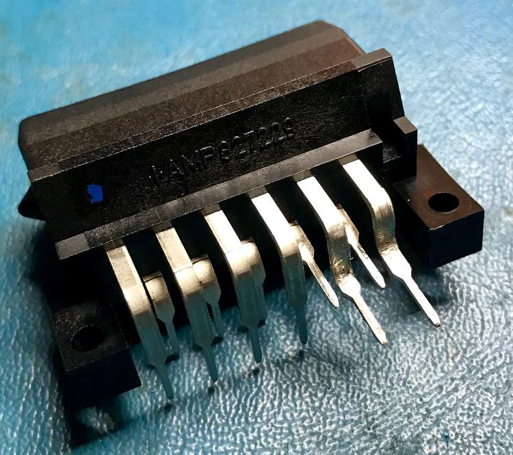 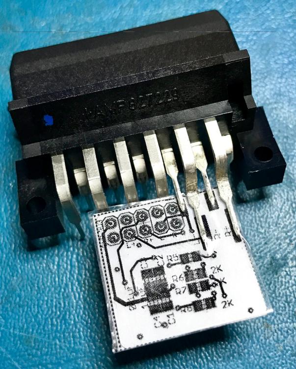 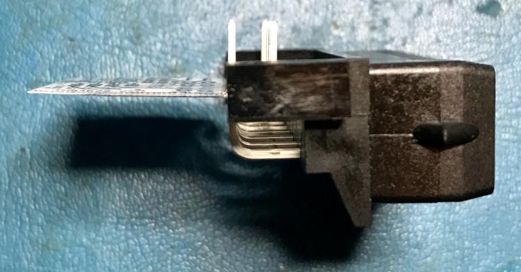 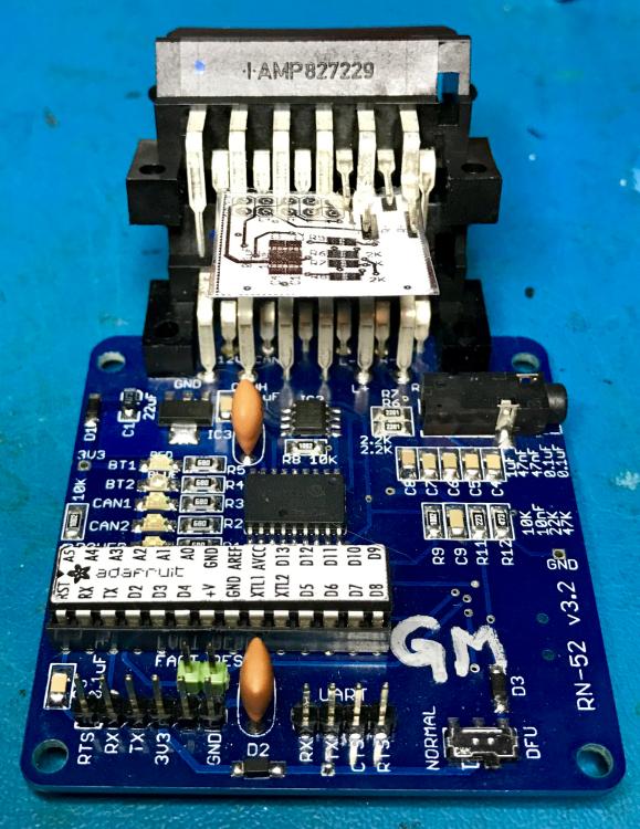
NC, USA
|
|
Nice work!
If this works it would be the perfect amp retrofit kit :-) I'm going to give it a try. |
|
Administrator
|
ok, STANDBY. sorry...i think i routed the wrong nets...working on it...
NC, USA
|
|
Administrator
|
Ok, got it. I had the wrong nets, but it's been fixed.
Anyone wanna be a guinea pig?  BlueSaab Amp PCB (THS4522 v1.2)
NC, USA
|
|
I'll give it a go :-)
Do you have a BOM? |
|
Administrator
|
«
Return to Hardware
|
1 view|%1 views
| Free forum by Nabble | Edit this page |

