Re: BlueSaab Legacy Amp PCB?
Posted by sbt on Nov 16, 2016; 2:45pm
URL: http://bluesaab-forum.90.s1.nabble.com/BlueSaab-Legacy-Amp-PCB-tp785p800.html
I was not suggesting using the amp pcb 1.1. I was suggesting a way to reduce the cost and messiness for retrofitting the legacy amp board inside the case, avoiding the need for any more connectors. You just need a pcb and components, so it shouldn't be much more than the amp v1.1, except due to square inches. But, you have to remove/desolder the CDC entirely from the old bluesaab module, and then re-solder it to the legacy amp. With the legacy amp board mounted upside down above the orginal PCB, the connector can still go through the hole in the plastic box. See extremely crummy diagram:
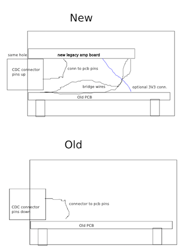
There should be enough wiring harness available in the car to twist through 180 degrees when mounting the box. The only additional wiring is 8 through hole connections with short lengths of hookup wire between the pcb holes on the edge of the legacy amp pcb and the pcb holes on the old module board where the CDC connector used to be. The only "messy" step is to desolder the connector; there's no cutting, bending or even trace cutting; all the bridge wiring is through-hole soldering (unless you delete the power supply and pickup 3.3V from the original board). Also, there's no more soldering than building the legacy amp outside the original BlueSaab with a flylead.
URL: http://bluesaab-forum.90.s1.nabble.com/BlueSaab-Legacy-Amp-PCB-tp785p800.html
Seth,
I was not suggesting using the amp pcb 1.1. I was suggesting a way to reduce the cost and messiness for retrofitting the legacy amp board inside the case, avoiding the need for any more connectors. You just need a pcb and components, so it shouldn't be much more than the amp v1.1, except due to square inches. But, you have to remove/desolder the CDC entirely from the old bluesaab module, and then re-solder it to the legacy amp. With the legacy amp board mounted upside down above the orginal PCB, the connector can still go through the hole in the plastic box. See extremely crummy diagram:
There should be enough wiring harness available in the car to twist through 180 degrees when mounting the box. The only additional wiring is 8 through hole connections with short lengths of hookup wire between the pcb holes on the edge of the legacy amp pcb and the pcb holes on the old module board where the CDC connector used to be. The only "messy" step is to desolder the connector; there's no cutting, bending or even trace cutting; all the bridge wiring is through-hole soldering (unless you delete the power supply and pickup 3.3V from the original board). Also, there's no more soldering than building the legacy amp outside the original BlueSaab with a flylead.
9³ 5D MY02 - Stålgrå, AS3; iOS 16.1; BlueSaab v5.0-p1+Amp v1.1, SAAB-CDC v4.1 with mods
| Free forum by Nabble | Edit this page |