Debugging my first 4.2 PCB

Previous Topic Next Topic
 
classic Classic list List threaded Threaded
5 messages Options
Reply | Threaded
Open this post in threaded view
|

Debugging my first 4.2 PCB

zurano
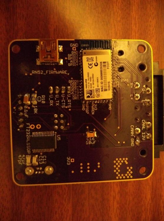
Finally I was able to solder my first PCB.

It was hard, but after some work all the components look good and no shortcircuits were found with a multimeter.

Anyway, It looks like it is not going to be easy  
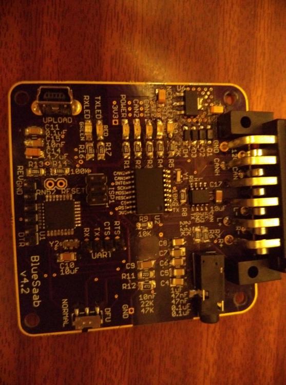
and I get normal blinking and voltage values for up to 5 seconds, after that tension from NCP1117 drops to 1.5v and LEDS start fading out. NCP zone goes pretty hot so my first though is that any component is putting 3.3v line to gnd after boot up.

Any thoughts or tips?
Saab 9-5 2.3t SE '98
Spain
Reply | Threaded
Open this post in threaded view
|

Re: Debugging my first 4.2 PCB

Seth
Administrator
Yeah, it sounds like you have a short to ground somewhere. check the RN52; they're easy to bridge. And it sounds like that might be the culprit, if you have code uploaded to the 328; it takes a few seconds to turn the RN52 on, and at that point is when you seem to have trouble.

If you want you can post pictures of your module; maybe there's something we can see?
NC, USA
Reply | Threaded
Open this post in threaded view
|

Re: Debugging my first 4.2 PCB

zurano
This post was updated on .
I was unable to upload code to the atmega because of the power going down also occurs when using an USB port. I have rechecked RN52 for bridges between adjacements contacts and everything looks ok.

Some images (from my phone, so not exatly HD):


Thank you for your help!
Saab 9-5 2.3t SE '98
Spain
Reply | Threaded
Open this post in threaded view
|

Re: Debugging my first 4.2 PCB

zurano
It was C16!

I borrowed a little thermal camera and it goes to <100ÂșC in seconds, I have removed it and now 3.3v is stable.

I am checking everything to see if the component is defective, I have made any mistake or the problem is with MCP2515, its oscillator or whatever.

Im close
Saab 9-5 2.3t SE '98
Spain
Reply | Threaded
Open this post in threaded view
|

Re: Debugging my first 4.2 PCB

Seth
Administrator
This post was updated on .
I'll Have to look at the layout but maybe C16 was backwards? I've switched to all ceramic caps and that one was polarized...but glad you got that fixed for now :)

Yeah, just looked at the layout; C16 was backwards. You're lucky it didn't blow up; tantalum caps HATE reverse polarity.

Don't use polarized caps. I intentionally left off polarity markings on all caps because I used ceramics.
NC, USA