Building myself a BlueSaab!
12


12
|
Hey all.
Just got all the parts from OSHPark, Mouser and Connectorpeople and I'm currently building my first bluesaab. When I'm done, I'll make a video about it and put it up on my Saab YouTube channel (Trionic Seven). Anyway, there seems to be a discrepancy between the parts list and pcb. I don't have that 100k resistor on the bottom that seems to do with the revision. Will I need it? Thanks all. I think there will be several questions as I get closer to finishing, I'll get back to you! |
|
From this thread:
"…R13/R14 are not needed at all right now; they are for future use." |
Re: Building myself a BlueSaab!
|
Great, thanks. That's what I suspected.
I'll try to continue the building process next week when I get back to the electronics lab. We'll see if I messed up the RN52 when learning SMD soldering! |
|
Administrator
|
Good luck!
Be generous with flux, use a good iron and have a steady hand! :)
2001 9-5 SE V6; 2006 9-5 Wagon; iOS; BlueSaab version = "latest and greatest" :)
|
Re: Building myself a BlueSaab!
|
So I think I got everything soldered up (except the usb connector...wow..those pins were so hard to get right I ended up de-soldering it completely).
I can input 12v to the correct pins but there is only light on the power led. Nothing else. Note that I haven't flashed any bootloader or software to the atmega yet. I am also not sure if all the chips survived the soldering. Maybe something's dead. Before I continue: Should I expect anything more than the power led when I connect 12v? The power draw of the whole system is around 14 mA. |
|
Administrator
|
When you apply power to the +/- pins, power LED should come up and BT1/BT2 LEDs should flash alternatively. The reason you are only seeing power LED coming up is like you said - there's no bootloader on ATMEGA328P-PU chip yet, so it can't "turn on" the software and pull the pins accordingly to apply power to RN52 Bluetooth chip.
Long story short - you should burn bootloader onto ATMEGA, then flash the chip with the latest code and then you should see power, BT1 and BT2 LEDs come up. Good luck! :)
2001 9-5 SE V6; 2006 9-5 Wagon; iOS; BlueSaab version = "latest and greatest" :)
|
Re: Building myself a BlueSaab!
|
Just what I wanted to hear, great! If you had said that the rn52 should power up on its own without an IC I would have become more worried.
I'm in the university electronics lab all on my own and I'm new to all this stuff. I have access to an avr jtagice3 flasher/debugger thing, but that one hat just a little cable going from it. Nowhere to put the atmega. I assume I can't flash via the pins on the bluesaab, right? |
|
Administrator
|
Unfortunately at the moment there's no way to flash bootloader onto ATMEGA while it's on BlueSaab module. I would say your best option os to put the ATMEGA chip on Arduino UNO board and use that to flash a bootloader.
I myself used this programmer that a friend of mine lent me: https://www.sparkfun.com/products/9825 I'm sure there's tons of different ways to get a bootloader onto ATMEGA, but I'm not quite "captain hardware". I'll let experts chime in on this (Seth I'm looking at you). :)
2001 9-5 SE V6; 2006 9-5 Wagon; iOS; BlueSaab version = "latest and greatest" :)
|
Re: Building myself a BlueSaab!
|
Agreed, I'm more of a software guy, completely new to embedded systems and soldering.
Let's continue this QA thread! I bought the boxes from Mouser, and I wonder how large I have to make the hole for the cdc connector. Just enough to fit the male plug, or do I need a few mm around the edge to fit the cdc cable, too? I'm not near my car at the moment. |
|
Administrator
|
You'll have to make a hole that is ~2-3mm larger than the connector itself. Otherwise it will be really hard to fit the assembled module into enclosure as you'll have to slide it in at an angle.
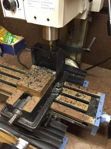
Having made like ten of these modules and enclosures, I just use my "test" module to match the size of connector, then mark it with a permanent marker and then use an automated mill to cut the hole. 
2001 9-5 SE V6; 2006 9-5 Wagon; iOS; BlueSaab version = "latest and greatest" :)
|
|
Administrator
|
So v4.0 of PCB (just finished; after testing confirms they are good, I'll release to the wild) has the ISP header for flashing a bootloader to the Atmega. This is also because the new pcb design went 100% SMD :) So removing the atmega is no longer an easy option and we need a way to burn bootloaders because atmegas with bootloaders preprogrammed are expensive for no reason.
Having said that, you'll need 2 arduinos if you wanna burn the bootloader to a blank 328 chip; one as the ISP (in system programmer) and one as the chip to be burned. It's easier to buy a bootloader burner like Karlis said, but if you're only doing 1 or 2 or 3, it's prob not worth it. You can google how to do it on a breadboard if you're only doing that many. It's just a few wires. I also have a template cut out of metal that I use to cut the hole for the cdc connector. The car's connector mates up to it fine with the connector protruding through the case; no need to cut the hole super large for the locking tabs; they lock fine.
NC, USA
|
Re: Building myself a BlueSaab!
|
Argh, 4.0? And I just almost completed the 3.3! :)
|
|
Administrator
|
Well, the only changes to v4.0 are that it's 100% SMD. Functionally and size-wize it's the same as v3.3. The code also is (and will be) designed so it works on all versions of PCB. So we're covered. And we are not quite sure yet if v4.0 will work. :)
2001 9-5 SE V6; 2006 9-5 Wagon; iOS; BlueSaab version = "latest and greatest" :)
|
|
Sorry for hijacking this topic ;)
Does v4.0 also have a Bluetooth 4.x chip? ;) would be great for the range (right now the music stutters when I have my iPhone in my pocket) and the battery life.
9-5 Estate MY2004/Aero/Glacier Blue/AS2
|
Re: Building myself a BlueSaab!
|
In reply to this post by Karlis
Yep, I got the connector on the bluesaab to fit in the box without problems, the question was if the car-side of the cable slides over the connector in such a way I will need extra space around the connector.
|
|
Administrator
|
In reply to this post by sloth
No, this is still bluetooth 3.0
NC, USA
|
|
Administrator
|
In reply to this post by Trionic Seven
no, the connector will fit fine without cutting an extra large hole.
NC, USA
|
|
In reply to this post by Seth
That's great news - adding the ICSP header brings it closer to being an Arduino. The requirement for having two Arduinos just to burn a bootloader seemed like overkill to me, so I went with a cheap USBasp programmer like this one (OSX and Linux have built-in drivers; it works with avrdude). |
|
In reply to this post by Trionic Seven
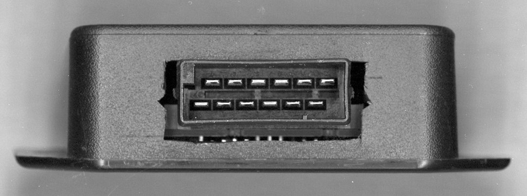
Here's a flatbed scan showing the brutish mess I made carving the connector hole with a hand drill + sharp knife.
Perhaps it might be useful to someone as a rough template. This is for a v3.3a PCB.  Since I was plugging/unplugging it many times during debugging, I trimmed down the little nubs on the sides of the connector to make things easier. |
Re: Building myself a BlueSaab!
|
Thanks all. I just finished building the module and uploaded the software.
Had to order a cd changer harness from Saab, will need to wait until next week for testing. |
«
Return to Hardware
|
1 view|%1 views
| Free forum by Nabble | Edit this page |

